Introduction
Starting with the definition, PDCP is an abbreviated form for Packet Data Convergence Protocol. PDCP protocol is defined by 3GPP specifications TS 38.323. As shown in the diagram below, this layer lies between RRC on the upper side and RLC on the lower side of the control protocol stack.
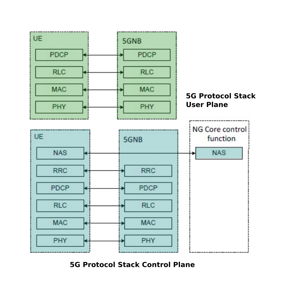
The figure shows the 5G NR protocol stack with the position of the PDCP layer. PDCP layer provides services to the upper layers that are, RRC or SDAP and takes few services and inputs from the RLC layer, MAC layer, and PHY layer.
With the help of the above figure, we can observe how the data flows through various protocol layers of 5G NR stack. As discussed above, PDCP provides some services to the upper layers, which are as follows:
- Transfer of data: user plane data and control plane data
- Header compression and decompression by making use of ROHC
- Ciphering and Deciphering of the user and control plane data
- Integrity protection
PDCP takes the following services by lower layers:
- Acknowledge of data transfer service
- Unacknowledged data transfer service
Now, let us discuss the functions of the PDCP layer.
Functions of PDCP Layer
- Transfer of data: user plane data and control plane data
- PDCP SNs' maintenance
- Compression and decompression of header by making use of ROHC protocol
- Ciphering and deciphering of data: user plane data and control plane data
- Integrity verification and protection of control plane data
- Timer-based SDU discard
- Routing or duplication for split bearers
- Activation and Deactivation of PDCP duplication
- Reordering and in-order delivery
- Discarding of duplicates
PDCP Architecture
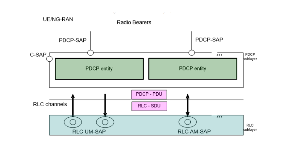
The diagram above depicts the architecture of PDCP which is based on radio interface protocol. PDCP sublayer is configured by RRC. Resource Blocks (RBs), which include DCCH and DTCH and are mapped on logical channels use this. Every resource block is associated with 1 entity of PDCP, which is, in turn, associated with 1 or 2 or 4 RLC entities which depend on RB characteristics or RLC modes. RB characteristics are split/non-split or uni-directional / bi-directional. The association of PDCP entity differs in the following ways for these RB characteristics:
- For split bearers: Every PDCP entity is related to two or four UM RLC entities or two AM RLC entities(same direction).
- For non-split bearers: Every PDCP entity is associated with one or two UM RLC entity or one AM RLC entity.
In the above diagram, we observe that the PDCP is directly connected to RLC Layer (RLC UM and RLC AM). This means that RLC TM mode has no connection with PDCP, which in turn means that RLC TM mode data does not go through PDCP.
Let us deep dive further into the diagram now starting from the left side.
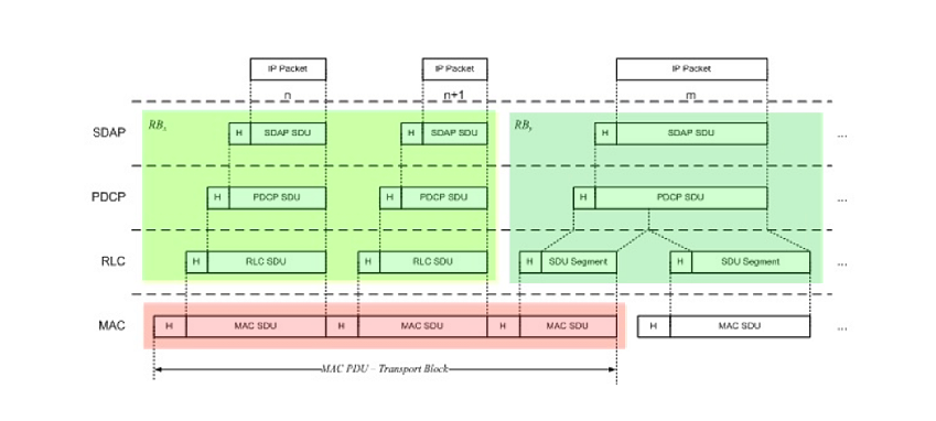
- When data enters the PDCP layer, it is first stored in a transmission buffer and then, goes through "Sequence Numbering" Procedure. PDCP adds "Sequence Number" to the incoming data blocks. Once the 'Sequence Number' has been added, this number has to be managed. At the receiver's end, we can interpret many things like "Is the data being delivered in order? Is there any duplication in data? How can multiple chunks of the data block be combined into an original big chunk data?"
- Now, the data goes through Header Compression. But there is a condition here, "this applies only to U-plane data". This means that Signaling Message does not go through this Header Compression. Although it is not shown in the diagram, Header Compression can be disabled even for U-plane data (e.g, IP Packet data).
-
Now onwards, there are two options. The first one is through "Integrity/Ciphering" and the other one skips this step and goes directly to the last step.
Integrity Protection applies only to C-Plane data (C-Plane data means RRC/NAS message, i.e DCCH data, not DTCH data). This "Integrity Protection" step can be disabled by applying a signaling message but we need to wait until RRC/NAS specification will come out with the details. - After this, it goes to the Ciphering process. Ciphering is applied to both C-Plane and U-Plane Data. This process can also be disabled by applying a signaling message but again, we need to wait until RRC/NAS specification will come out with the details.
- Fifth step here is that a PDCP header gets added.
- The PDCP routs the packet to the intended bearer if the Split bearer is established.
The right side of the diagram follows the reverse of the transmission process. Hope this can be left to the readers for self-interpretation.
PDCP Entity

Following is a brief description of the PDCP Entity:
- The PDCP entities are positioned in the PDCP sublayer. Numerous PDCP entities may be defined for a UE. The data of one radio bearer is carried by every PDCP entity.
- Depending on which radio bearer the PDCP entity is carrying data for, it is associated either to the control plane or the user plane.
- The figure here depicts the functional view of the PDCP entity used for the PDCP sublayer.
- The data can be in two forms: compressed PDCP SDU and uncompressed PDCP SDU. Compressed data is associated with user plane only whereas, Uncompressed data is associated with the user plane or control plane.
- PDU can also be of two types depending on the plane: control PDU or data PDU. Control PDU type includes either PDCP status report or interspersed ROHC feedback.
The overall functionality of NR PDCP is very similar to LTE PDCP. Few of the differences have been highlighted in the diagram below.

PDCP Procedures for data transfer
-
There are three PDCP entity handling procedures namely,
- PDCP entity establishment
- PDCP entity re-establishment
- PDCP entity release
- After the establishment process, PDCP procedures are linked with two operations: transmitting or receiving operation.
- During the transmit operation, the PDCP entity receives SDU from the upper layer. On the SDU that is received, several operations are performed before it is given to lower layers. It is later passed to a radio interface (Uu).
- A vice-versa process is followed between UE and NG-RAN as to UE transmits - NG-RAN receives and NG-RAN transmits - UE receives.
- Similar kind of procedure is performed when data PDU is received from lower layers.
- Size of PDCP SDU and PDCP control PDU are maximum 9000 bytes.
- The length of PDCP SN is either 12 bits or 18 bits. It is configured by upper layers.
PDCP layer data PDU and control PDU formats
- A PDCP PDU is a bit string and is aligned by bytes, that is a multiple of 8 bits, in length.
- A PDCP SDU is a bit string and is aligned by bytes, that is, a multiple of 8 bits, in length.
- From the first bit of the PDCP Data PDU, a compressed or uncompressed SDU is included.
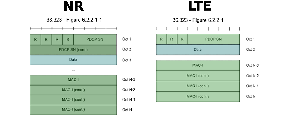
- The below figure represents PDCP Data PDU format with 12 bits PDCP SN. This format fits for SRBs.
Data PDU for SRB
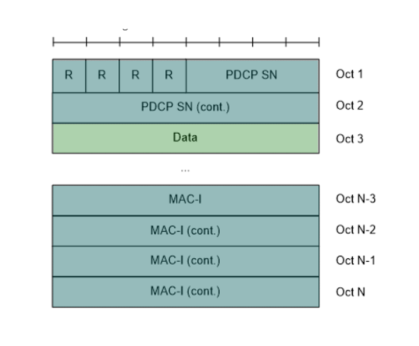
[38.323 - Figure 6.2.2.1-1: PDCP Data PDU format for SRBs]
Below diagram shows the comparison between NR SRB PDCP and LTE SRB PDCP data structure. You will observe that the overall structure is the same except that SN length in NR is much larger than LTE SRB PDCP.
Data PDU for DRB
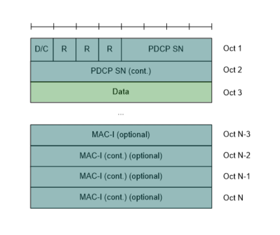
[38.323 - Figure 6.2.2.2-1: PDCP Data PDU format with 12 bits PDCP SN]
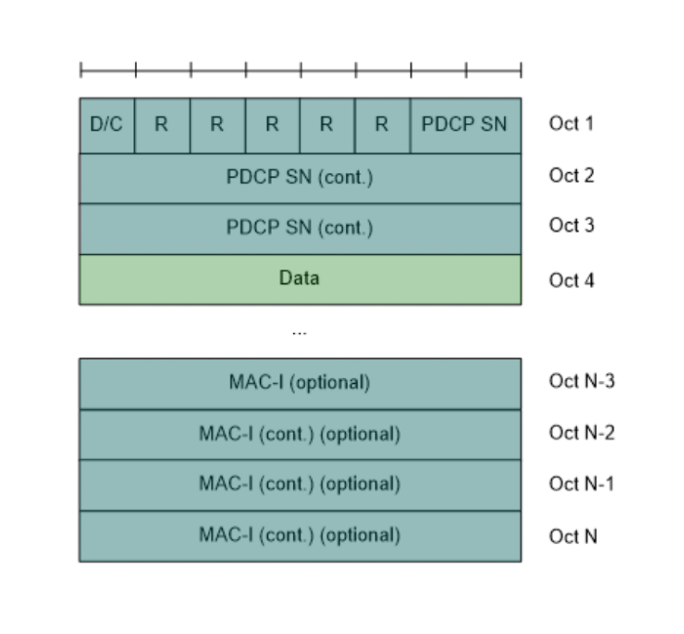
[38.323 - Figure 6.2.2.3-1: PDCP Data PDU format for DRBs with 18 bits PDCP SN]
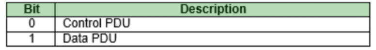
[38.323 - Table 6.3.7-1: D/C field]

[38.323 - Table 6.3.2-1: PDCP SN length]
Control PDU

[38.323 - Figure 6.2.3.1-1: PDCP Control PDU format for PDCP status report ]
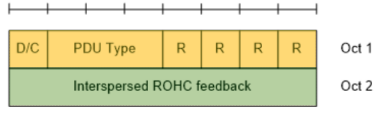
[38.323 - Figure 6.2.3.2-1: PDCP Control PDU format for interspersed ROHC feedback]

[38.323 - Table 6.3.7-1: D/C field]
[38.323 - Table 6.3.8-1: PDU type]
[38.323 - Table 6.3.10-1 Bitmap]